Looking back on my tutorial, that may be the problem. My statement is ambiguous as to whether the eeprom connects to pin 5 of the logic or if the cart edge connects to the logic.
Pin 5 of the 74xx00 is an input, not an output. So what we are doing here is connecting two inputs together - nothing happens.
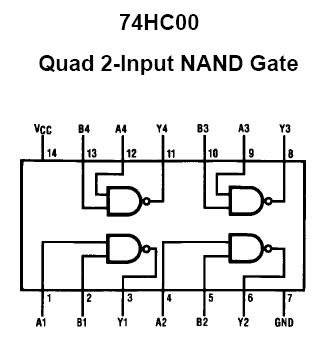
The 74xx00 is being used as a simple logic-based memory mapper comprised of only NAND gates (not and). The locations within the memory map for each IC can be determined with some logic equations. For example (not literally, but probably close):
IC_ROM = ~(CE*A20)
IC_RAM = ~CE*A20
So (still not being literal) when CE is low and A20 is low, ROM is enabled. When CE is low and A20 is high, RAM is enabled (ROM is disabled). That being said, we should be using A21 and not A20 if you want 2MBytes of ROM. A20 on the cart edge is actually A21 and 2^21 equals 2Mbytes which is split in half for each IC. The first 1Mbyte is allocated to ROM and the second 1MByte is allocated to RAM. I realize this is a bit much and difficult to explain.
What I mean to say is that I should edit my tutorial and be more clear. no one has questioned it before, so I guess it stayed incorrect for a long time. hehe
So.....
To clear everything up, first, what game are you trying to burn? How big is it? Does it only fill half of the 27c322? If the game is only 1Mbyte, we can connect pin A20 of your eeprom to ground and solve the issue. I think.
If your game is actually 2Mbytes, we will have to work a little harder.


Originally Posted by gamemaster76


